[JASA 1C2] SoC Harness Functions User Logic Debug – Caravel SoC
Version: 2024/05/29
Table of Contents:
To evaluate the feasibility of realizing the JASA Chip 1 using eFabless design and manufacturing processes, we will assess the “user circuit debug function” using the “Marmot1” logic placed in the MPW-6 open project area. This evaluation involves creating a Caravel program and testing its functionality. By running “Marmot1” on MPW-6, we aim to demonstrate the design flow intended for use in JASA Chip 1.
Please follow the software setup in the previous investigation.
| Caravel mprj_io[#] | Caravel Mgmt. SoC | Marmot IOF0 | Marmot GPIO |
|---|---|---|---|
| 0 | JTAG | – | – |
| 1 | SDO | TDO | – |
| 2 | SDI | TDI | – |
| 3 | CSB | TMS | – |
| 4 | SCK | TCK | – |
| 5 | ser_rx | uart0_rx | – |
| 6 | ser_tx | uart0_tx | – |
| 7 | irq | spi1_csb[1] | gpio[24] |
| 8 | flash2_csb | spi0_flash_csb | – |
| 9 | flash2_sck | spi0_flash_sck | – |
| 10 | flash2_io[0] | spi0_flash_io[0] | – |
| 11 | flash2_io[1] | spi0_flash_io[1] | – |
| 12 | – | spi0_flash_io[2] | – |
| 13 | – | spi0_flash_io[3] | – |
| 14 | – | spi1_csb[0] | gpio[0] |
| 15 | – | spi1_sck | gpio[1] |
| 16 | – | spi1_io[0] | gpio[2] |
| 17 | – | spi1_io[1] | gpio[3] |
| 18 | – | spi1_io[2] | gpio[4] |
| 19 | – | spi1_io[3] | gpio[5] |
| 20 | – | spi2_csb | – |
| 21 | – | spi2_sck | – |
| 22 | – | spi2_io[0] | – |
| 23 | – | spi2_io[1] | – |
| 24 | – | spi2_io[2] | – |
| 25 | – | spi2_io[3] | – |
| 26 | – | i2c0_sda | gpio[12] |
| 27 | – | i2c0_scl | gpio[13] |
| 28 | – | i2c1_sda | gpio[14] |
| 29 | – | i2c1_scl | gpio[15] |
| 30 | – | uart1_rx | gpio[16] |
| 31 | – | uart1_tx | gpio[17] |
| 32 | – | uart2_rx | gpio[18] |
| 33 | – | uart2_tx | gpio[19] |
| 34 | – | uart3_rx | gpio[20] |
| 35 | – | uart3_tx | gpio[21] |
| 36 | – | uart4_rx | gpio[22] |
| 37 | – | uart4_tx | gpio[23] |
Ensure the Caravel board is powered off before starting the setup.
Ensure that the M.2 card with Marmot1 MPW-6 is properly inserted into the M.2 connector and securely fastened with a screw.。
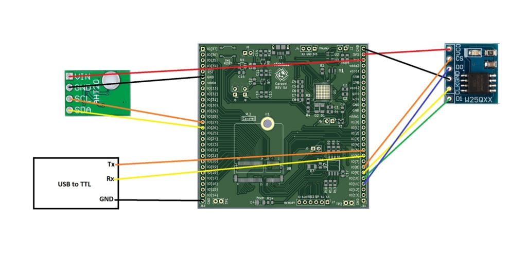
Connect an external SPI Flash module W25Q32 (flash2) to the Caravel board as below:
| Caravel Board | Marmot IOF0 | Flash2 |
|---|---|---|
| 3V3 | VCC | |
| GND | GND | |
| mprj_io[8] | spi0_flash_csb | CS |
| mprj_io[9] | spi0_flash_sck | CLK |
| mprj_io[10] | spi0_flash_io[0] | DI |
| mprj_io[11] | spi0_flash_io[1] | DO |
Connect an AHT20 sensor module to the Caravel board as below:
| Caravel Board | Marmot IOF0 | AHT20 |
|---|---|---|
| 3V3 | VIN | |
| GND | GND | |
| mprj_io[26] | i2c0_sda | SDA |
| mprj_io[27] | i2c0_scl | SCL |
And the USB to TTL module (3.3V) as below:。
| Caravel Board | Marmot IOF0 | USB to TTL |
|---|---|---|
| GND | GND | |
| mprj_io[5] | uart0_rx | Tx |
| mprj_io[6] | uart0_tx | Rx |
Our hardware setup is now complete and ready for testing.
Run below commands to build the firmware and flash it to the Caravel Management SoC:
cd ~/caravel_samples/picorv32/marmot
make clean
make
sudo make flash
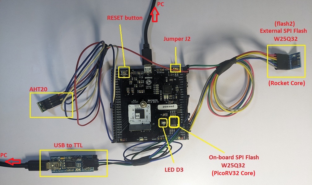
After flashing the firmware to the PicoRV32 Core, the LED D3 on Caravel board will start blinking.
The firmware for the Rocket Core will be put in the external SPI flash memory “flash2” (W25Q32).
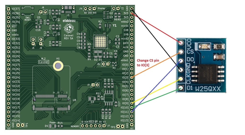
To flash the external SPI Flash (W25Q32), we will use the user passthru mode.
At first, we need to connect the CS pin of SPI Flash to mprj_io[3] instead of mprj_io[8].
Run below commands to build the firmware and flash it to the external SPI flash memory:
cd ~/caravel_samples/rocket/hello
make clean
make
sudo make flash2
After flashing the “flash2”, we need to reconnect the CS pin to mprj_io[8] so that the Rocket core can access and execute commands from the SPI Flash memory.
Press RESET button and we can see the Rocket Core output via UART (baudrate 115200).。
Follow the steps below:
cd ~/caravel_samples/rocket/gpio
make clean
make
sudo make flash2
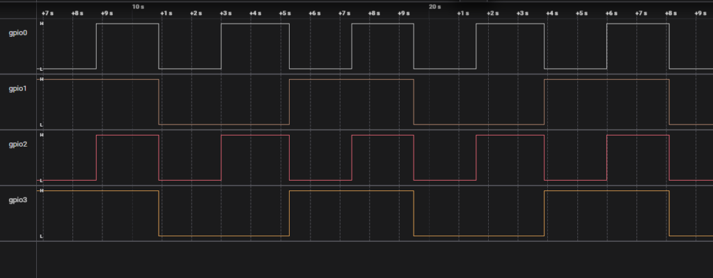
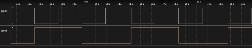
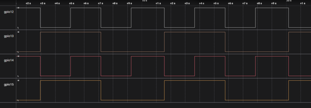
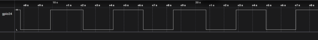
We could get the signal from gpio pins.
Please check the table Pinouts for the corresponding pin.
For example, gpio0 is mprj_io[14] on the Caravel board.
| Caravel mprj_io[#] | Caravel Mgmt. SoC | Marmot IOF0 | Marmot GPIO |
|---|---|---|---|
| 5 | ser_rx | uart0_rx | – |
| 6 | ser_tx | uart0_tx | – |
| 30 | – | uart1_rx | gpio[16] |
| 31 | – | uart1_tx | gpio[17] |
| 32 | – | uart2_rx | gpio[18] |
| 33 | – | uart2_tx | gpio[19] |
| 34 | – | uart3_rx | gpio[20] |
| 35 | – | uart3_tx | gpio[21] |
| 36 | – | uart4_rx | gpio[22] |
| 37 | – | uart4_tx | gpio[23] |
Follow the steps below:
cd ~/caravel_samples/rocket/uart
make clean
make
sudo make flash2
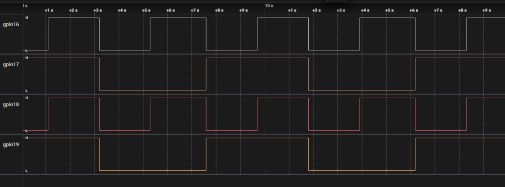
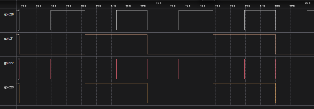
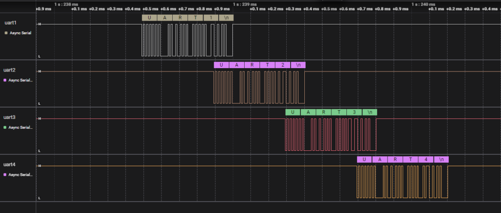
We could see the output from UART0:
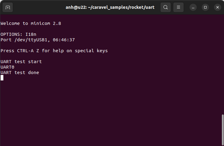
And UART1 – UART4
| Caravel mprj_io[#] | Marmot IOF0 |
|---|---|
| 26 | i2c0_sda |
| 27 | i2c0_scl |
| 28 | i2c1_sda |
| 29 | i2c1_scl |
Follow the steps below:
cd ~/caravel_samples/rocket/i2c
make clean
make
sudo make flash2
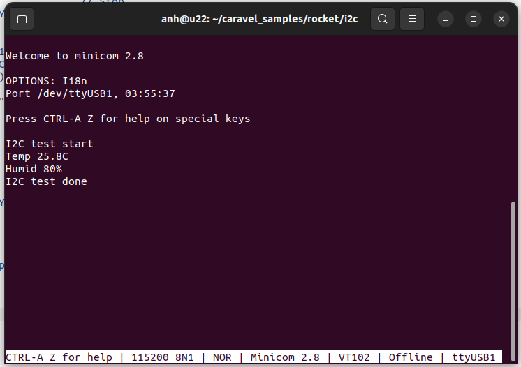
We can read the temperature and humidity from AHT20 sensor and output them to UART0.
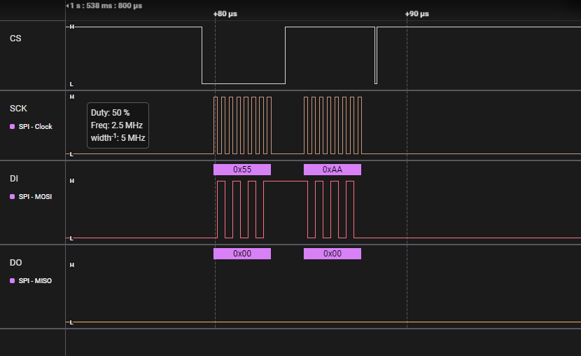
| Caravel mprj_io[#] | Marmot IOF0 |
|---|---|
| 14 | spi1_csb[0] |
| 15 | spi1_sck |
| 16 | spi1_mosi |
| 17 | spi1_miso |
Follow the steps below:
cd ~/caravel_samples/rocket/spi
make clean
make
sudo make flash2
The logic analyzer is a 128-bit port going to/from the user area and management SoC. It allows the SoC to “probe” any desired signals from the user area after fabrication (but they cannot be changed once fabricated). This is useful for debugging signals during the bringup process, possibly to discover bugs in the hardware, or to verify that they are working correctly.
In the Marmot1 user logic, the lowest 32-bit port is connected to gpio0 – gpio31.。
To run LA test, follow the steps below:
cd ~/caravel_samples/picorv32/la
make clean
make
sudo make flash
cd ~/caravel_samples/rocket/gpio
make clean
make
sudo make flash2
We could get logs on UART0 from PicoRV32. The baud rate of PicoRV32 UART is 9600.
Copyright © Japan Embedded Systems Technology Association All Rights Reserved.